PROJECT #4 - Trying Out BMP280 External Sensor On ESP32 Dev Board Using The Arduino IDE
Hello again! This time I'm going to try using an external sensor on my ESP32 since last week I've tried using the ESP32's internal sensor. For the sensor, I'm using a BMP280 barometric pressure module that consists of 3 sensors: temperature, air pressure, and altitude. Without further ado, let's get to the project!
STEP 1: Prepare The Required Software and Hardware
For hardware, you'll need these components:
- ESP32 Development Board
- Breadboard
- Jumper Wire Male-to-Male
- BMP280 Barometric Pressure Module
 |
| BMP280 |
STEP 2: Set Up The Hardware
Firstly, put the ESP32 Dev Board and the BMP280 on the breadboard. After that, connect a jumper wire from the ESP32 pins to the BMP280. For the details, see below :
- 3V3 pin (dev board) to VCC pin (sensor)
- GND pin (dev board) to GND pin (sensor)
- GPIO 22 pin (dev board) to SCL pin (sensor)
- GPIO 21 pin (dev board) to SDA pin (sensor)
You can refer to the image below for reference.
 |
| BMP280 Pin Location |
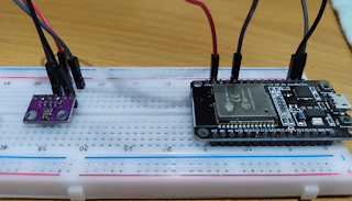 |
| Circuit View |
STEP 3: Program The Dev Board
For this project's program, I'm using an example sketch file from the Adafruit BMP280 Library. If you haven't installed it yet, you can go to Tools -> Manage Libraries then search "Adafruit BMP280" and click install. Make sure you install all the libraries when prompted "install all" or "install this only".
 |
| Adafruit BMP280 Library Location |
After you install the library, you can go to Examples -> Adafruit BMP280 Library (Scroll down if you didn't find it) -> bmp280test to access the program I'm using for this project.
 |
| bmp280test Sketch File Location |
 |
| bmp280test Sketch Code (1) |
 |
| bmp280test Sketch Code (2) |
After preparing the sketch file, verify and upload the program to the ESP32.
STEP 4: Check The Result and Debug If Necessary
After resetting the Dev board, go to Serial Monitor to see the result of the sensor's reading. The result should be like in the image below.
 |
| Experiment View |
 |
| Sensor Result |
If you see an error message like the image below, you must use the I2C scanner program to scan for the sensor's address. You can get the sketch code here. After getting the address, insert it to the first program (bmp280test) in the bmp.begin("address goes here"). Then you can re-upload the program and test it again.
 |
| Error Message |
 |
| I2C Scanner Result |
That's all for this project! Thank you for reading and happy experimenting!
- Ryu / 18220025


Comments
Post a Comment