Hey there! For my first project, I'm going to try starting up my ESP32 Development Board and programming it to make its LED blink. I'm going to split this into 2 parts, internal LED and external LED using a resistor and jumper wire. For this project, you'll need :
1. ESP32 Development Board
The focus of this project. You can use other Development Board.
 |
| ESP32 Development Board |
2. Laptop / PC
The power source of the Dev board and for programming the Dev board. I'm using Windows 10 Desktop PC for this project.
 |
| Laptop |
3. Micro-USB Cable
To connect the Dev board to the laptop / PC.
 |
| Micro-USB Cable |
4. LED
To see the result of the program.
 |
| LED |
5. 330 Ohm Resistor
The resistor is used to limit the current that goes through the LED so that the LED doesn't get overheated and destroyed.
 |
| 330 Ohm Resistor |
6. Jumper Wire Male-to-Male
To connect the ESP32 Dev Board to the external LED.
 |
| Jumper Wire Male-to-Male |
7. Breadboard
A device for making temporary circuit.
 |
| Breadboard (Note: the white one on the background) |
Now, let's get started!
PART 1: INTERNAL LED
STEP 1: Download and Configure The Required Software
1. Download and install Arduino IDE. You can download it from this link: https://www.arduino.cc/en/software.
 |
| Arduino IDE Download Website |
2. Configure the app by going to File → Preferences. After the menu pop-up, paste this link (https://dl.espressif.com/dl/package_esp32_index.json) into the Additional Boards Manager URLs and click OK.
 |
| Preferences Location |
 |
| Preferences Menu |
3. Choose and set the Dev board you're using in the Tools menu. If you didn't find the Dev board you're using, go to Tools → Board → Boards Manager and install the Dev board you're using. In my case, I install the esp32 package to use the DOIT ESP32 DEVKIT V1 board.
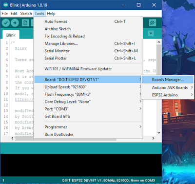 |
| Boards Manager Location |
 |
| Boards Manager Menu |
 |
| Select the Dev Board |
4. Download and install USB to UART Driver. You can download it from this link: https://www.silabs.com/developers/usb-to-uart-bridge-vcp-drivers. (Note: if you've downloaded the CP210x Universal Windows Driver, you may have to install it manually. Look at the Release Notes to find the install method)
 |
| USB to UART Driver Download Website |
 |
| Manual Installation |
STEP 2: Connect The Dev Board
1. Connect the Dev board using the micro-USB cable to the laptop / PC. You can check if the Dev board is powered or not by looking at the red internal LED in the Dev Board.
 |
| Red Light from The Internal LED Indicating The Dev Board is Powered |
2. Check the Port in Tools → Port. If the Dev board is connected, it shouldn't be greyed out and you can choose the port you're using (Note: if you're using Desktop PC, the port name may come out as COM(number)). If the port is greyed out, you can try to unplug and plug the micro-USB cable and if it is still greyed out, you may want to consider trying another micro-USB cable or maybe the USB to UART Driver is not correctly installed.
 |
| Port Connected |
STEP 3: Program The Dev Board
For the first project, I'm going to use the Blink source code from the examples. You can open this source code from File → Examples → 01. Basics → Blink.
 |
| Blink Source Code Location |
After you open the source code, you can click the checklist button (verify) on the top left side of the app to compile the code.
 |
| Verify Button Location |
 |
| Done Compiling Example |
After the app has done compiling, you can click the right arrow button (upload) beside the verify button to upload the program to the Dev board.
 |
| Upload Button Location |
If you encounter an error message "A fatal error occurred: Failed to connect to ESP32: Timed out waiting for packet header", you can try clicking the upload again, and when the terminal shows a "Connecting..." message, click and hold the BOOT button on the Dev board until the terminal is changed. After it's done uploading, click the EN button on the Dev board to reset the board and the program should be running.
 |
| Error Message Example |
 |
Connecting Example
|
 |
| BOOT and EN Button Location |
 |
| Done Uploading Example |
STEP 4: Observe The Dev Board
If the program is running, the blue build-in LED in the Dev Board should be blinking. And that's it for the first part!
PART 2: EXTERNAL LED
STEP 1: Setup The Dev Board in The Breadboard
The breadboard connection is explained in the image below.
 |
| The Breadboard Connection |
Gently put the Dev board on the breadboard until all of the Dev board's legs connect to the breadboard. After that, put the external LED somewhere in the breadboard but be careful not to place both legs on the same connection.
 |
| After The Setup (Note: the longer part of the LED is the left one) |
STEP 2: Connect The Dev Board to The External LED Using Jumper Wire
Using the jumper wire, connect D5 (you can use another GPIO* number from 2 / 4 - 5 / 13 - 33) to the longer part of the external LED (the positive one). After that, connect the shorter part of the external LED to the 330 ohm resistor. Lastly, connect the other part of the resistor to the ground (GND) of the Dev board. you can use a jumper wire to connect those 2. Refer to the image below for more.
*GPIO = General-Purpose Input / Output. The one on both sides of the Dev Board.
 |
| Above View (I connect to D5 for the output) |
 |
| Rear View |
STEP 3: Program The Dev Board
The source code for the second part is based on the Blink source code from the first part. You just have to change the output part from LED_BUILDIN to the GPIO pin number. You can see more in the image below.
 |
| Program For External LED Blinking |
STEP 4: See The Result and Debug If Necessary
This is the result if the setup you made is correct. If the program and the setup are right, the external LED should be blinking.
Thank you for reading this blog and happy experimenting! ^^
Ryu / 18220025 -


Comments
Post a Comment