PROJECT #5 - Trying Out OLED Display and Pulse-Width Modulation On ESP32 Dev Board Using The Arduino IDE
Hello there! Welcome to my next project! After last week's project theme is around sensors, this week's theme is output. I'm going to try using an OLED display to display something and using LEDs to simulate Pulse-Width Modulation (PWM) on ESP32. Now sit tight and grab your popcorn, because this week's project is going to be a lot of experiments!
PART 1: OLED DISPLAY
STEP 1: Prepare The Required Software and Hardware
For hardware, you'll need these components:
- ESP32 Dev Board
- Breadboard
- Jumper Wire Male-to-Male
- OLED Display (I'm using OLED 0.96 inch 128x64 Display Module)
 |
| OLED Display |
For software, you'll need to set up the Arduino IDE. If you haven't set it up yet, you can click here to see the installation process from my first project in the first step from the first part.
After you set up the Arduino IDE, you'll need an extra library to use the OLED display. To install the library, simply go to Manage Libraries and download "Adafruit SSD1306" and "Adafruit GFX Library".
 |
| Adafruit SSD1306 |
| Adafruit GFX Library |
STEP 2: Set Up The Hardware
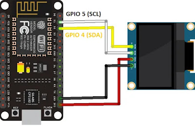
Set your ESP32 Dev Board and OLED display on the breadboard. Then, connect these pins using jumper wire:
- 3V3 pin (dev board) to VCC pin (OLED)
- GND pin (dev board) to GND pin (OLED)
- GPIO 22 pin (dev board) to SCL pin (OLED)
- GPIO 21 pin (dev board) to SDA pin (OLED)
All of the first part's experiments are going to use this setup.
 |
| Wiring Scheme |
 |
| Hardware Setup |
STEP 3: Testing The OLED Display
After buying the OLED display, we have to test it to see whether our display is functioning or not. To do this, we're going to use the example file from Adafruit SSD1306 Library. Go to File -> Examples -> Adafruit SSD1306 -> ssd1306_(your module resolution)_i2c to access the example file. I'm using the ssd1306_128x64_i2c file. Now see your OLED display. If your display doesn't have a RESET PIN, you should set the OLED_RESET variable to -1 and to your pin number if the display does have a RESET pin. Do the i2c scanner too, to see what's the address of your display. You can get the i2c scanner here. Change the SCREEN_ADDRESS variable too if the value is different from the i2c scanner result.


The result should be like this :
STEP 4: Displaying and Scrolling Text On OLED
After testing your OLED display, we're going to try writing something and make that text scroll sideways. You can get both source codes from here and here. Or you can see the source code below.
 |
| Writing Text Code |
 |
| Text Scrolling Code (1) |
 |
| Text Scrolling Code (2) |
The result should be like this :
 |
| Writing "Hello, World!" |
Text Scrolling result:
STEP 5: Changing The Text's Font
You can change the text's font by using the corresponding font file. This is the selection of font that you can choose :
 |
| Font Selection |
Note that the 9 and 12 points size are the fonts that work better with the OLED display.
I'm going to use this source code that you can copy from here or look at the image below.
 |
| Change Font Code |
The result should be like this:
 |
| Writing "Hello, World!" With Different Font |
STEP 6: Drawing Shapes
We can draw a shape too using the corresponding command. You can see the command here or look at the image below.
 |
| Drawing Shape Code (1) |
 |
| Drawing Shape Code (2) |
 |
| Drawing Shape Code (3) |
Each result will be like in the video:
STEP 7: Displaying Bitmap Image
It's a bit complicated, but it's doable to display a bitmap image from your computer to the OLED display. First, we have to resize (change the size to your display resolution) and change the photo format to monochrome bitmap. You can do this using Paint if you're using Windows. After that, use an image to C array converter to convert the image into a code array. For this, I'm using LCD Image Converter. After you convert the image, copy the array to the source code below (change the "static const uint8_t" line to the new array). You can get the source code here or look at the image below. Note that you have to replace the array with your image's array and change the variable's name in the display.drawBitmap code.
 |
| Bitmap Image Display Code (1) |
 |
| Bitmap Image Display Code (2) |
Here's the result:
 |
| Bitmap Image Display |
And that's it for the first part!
PART 2: PULSE-WIDTH MODULATION
STEP 1: Prepare The Required Software and Hardware
For hardware, you'll need these components:
- ESP32 Dev Board
- Breadboard
- Jumper Wire Male-to-Male
- LEDs
- 330 ohm Resistor
For software, you'll need to set up the Arduino IDE. See the first part's first step above if you haven't set up the software.
STEP 2: Set Up The Hardware
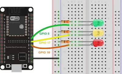
Make a circuit as in the following image. But, you can replace the GPIO pin with any other pin that can be used for output.
 |
| Wiring Scheme |
 |
| Hardware Setup |
Set up two other LEDs circuit that looks like the first setup. This is for the second experiment of this part. Look at the image below for reference:
 |
| Wiring Scheme |
 |
| Hardware Setup |
STEP 3: PWM 1 LED
You can copy the source code here or look at the image below. Change the ledPin variable's value to the pin you choose for your experiment.
 |
| PWM 1 LED Code |
The result should be like this:
You can use the same signal from the same channel to different GPIO pins. We're going to try that in step 4.
STEP 4: PWM 3 LEDs
You can copy the source code here or look at the image below. Change the ledPin variable's value to the pin you use for your experiment.
 |
| PWM 3 LEDs Code |
The result should be the same as in step 3, but this time, all of the LEDs are lighted up instead of just one LED. Look at the video below for the result:
And that's it for this project! Thank you for reading and happy experimenting! ^^
- Ryu / 18220025


Comments
Post a Comment